They also should take care again of the rule of hands. Inch Units Applicable for Constants Spur Gear Design Calculator. Bevel gear design formula.
Bevel Gear Design Formula, Bevel gears are most often mounted on shafts that are 90 degrees apart but can be designed to work at other angles as well. For bevel gearing when the number of teeth in the pinion is equal to the number of teeth in the bevel gear the speed ratio becomes 11 and these are called miter gears. Calculation of gear ratio i and pitch angle. Bevel gears can include straight spiral Zerol hypoid and.
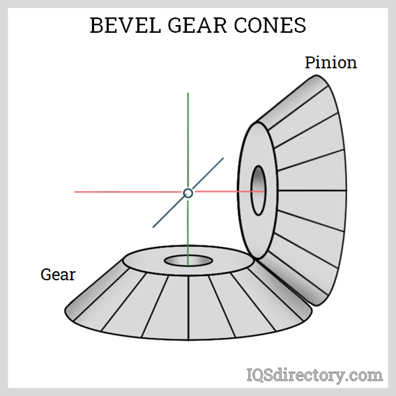 Bevel Gear What Is It How Does It Work Types Uses From iqsdirectory.com
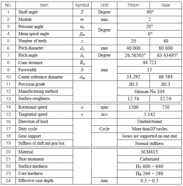
Formula of bevel gears on bending strength JGMA403-01 The Lewis formula. D 1 z 1 m. The calculation equations of Table 416 for Gleason straight bevel gears are applicable. Speed of pinion and gear are Np 500 RPM and Ng 250 RPM respectively.
Left-hand and right-hand as a pair.
Read another article:
Computerized Design of Straight Bevel Gears with Optimized Profi les for Forging Molding or. The further from the intersection of the gear and pinion axes the bigger the tooth cross sections are. Of teeth of mating gear No. Design a pair of bevel gear which is used to connect two shaft at right angles and transmit P 50 kW power from an induction motor to a conveyor belt. They also should take care again of the rule of hands.
 Source: gearsolutions.com
Boston Gear has an excellent document on the formulas and geometry at this link. Design procedure for Bevel Gear. Bevel gears are classified accordingto their type of the tooth forms into Straight Bevel Gear Spiral Bevel Gear Zerol Bevel Gear Skew Bevel Gear etcThe meshing of bevel gears means the pitch cone of two gears contact and roll with each other. Over 10 7 cycles Impact from motor. Cones Are Not Just For Ice Cream Gear Solutions Magazine Your Resource To The Gear Industry.
 Source: baoxincz.com
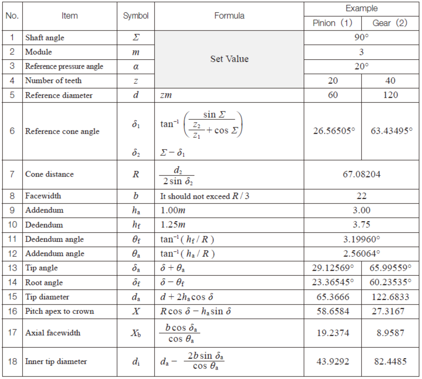
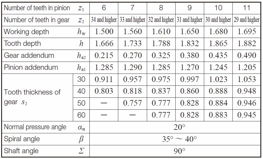
The following online calculator computes the basic dimensions and tooth profiles of a bevel gear pair pinion and gear based on their number of teeth and angle between the shaft axes. Spur Gear and Assembly Builder - Download DXF SVG Spur Gear design formula for geometry pitch tooth clearance and critical functional data. In the last stage of gear design when gear dimensions are recognized errors are particular and the quality of gear is resolute the dynamic load. Of teeth of mating gear. Gleason Spiral Bevel Gears Calculation.
 Source: vortarus.com
To optimize the performance of any two bevel gears the gears must be positioned together so that they run smoothly without binding andor excessive backlash. Bevel gears are gears where the axes of the two shafts intersect and the tooth-bearing faces of the gears themselves are conically shaped. In the last stage of gear design when gear dimensions are recognized errors are particular and the quality of gear is resolute the dynamic load. If the tooth face were to extend all the way to the axes intersection the teeth would approach infinitesimal size. Spiral Bevel Gear Forces Vortarus Technologies Llc.
 Source: iso.org
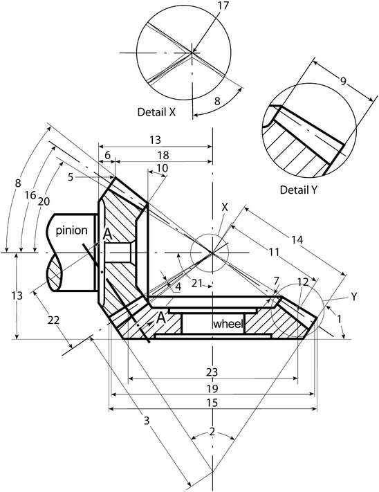
Bevel gears can include straight spiral Zerol hypoid and. They also should take care again of the rule of hands. The calculation equations of Table 416 for Gleason straight bevel gears are applicable. Of teeth of mating gear No. Iso 23509 2006 En Bevel And Hypoid Gear Geometry.
 Source: link.springer.com
Bevel gears can include straight spiral Zerol hypoid and. Bevel gears can be also used for only changing the rotation direction of power transmission which are called miter gears. If the tooth face were to extend all the way to the axes intersection the teeth would approach infinitesimal size. Velocity factor for bevel gear is given as here C R v 56 56 v Where v is the pitch line velocity in ms. Fundamentals Of Bevel Gears Springerlink.
 Source: kktechnicalinfo.blogspot.com
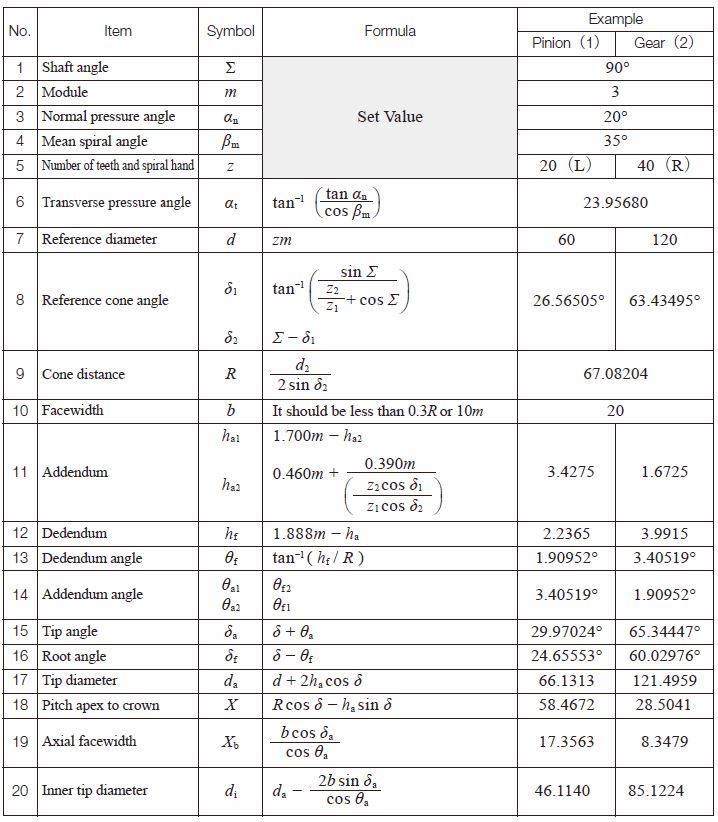
Of teeth of the mating gear of the set Rotational Speed. The calculation equations of Table 416 for Gleason straight bevel gears are applicable. Left-hand and right-hand as a pair. Finally calculate YF by Equation 1034. Engineeringtechnical Info Calculation Of Gear Dimensions.
 Source: khkgears.net
Formula of bevel gears on bending strength JGMA403-01 The Lewis formula. Speed of pinion and gear are Np 500 RPM and Ng 250 RPM respectively. Finally calculate YF by Equation 1034. Velocity factor for bevel gear is given as here C R v 56 56 v Where v is the pitch line velocity in ms. Bending Strength Of Bevel Gears Khk Gears.
 Source: sciencedirect.com
A spiral bevel gear set requires matching of hands. φ Pressure Angle a Addendum a G Addendum of Gear a P. The allowable tangential wear load F w is calculated as follows F w d p. γ 1 γ 2 Σ γ 1 2 In case of a 90 shaft angle the relationship will simplify to. Bevel Gears An Overview Sciencedirect Topics.
 Source: sdp-si.com
Cone-shaped bevel gears are produced for the power transmission between these shafts. Of teeth of mating gear. Lp atanNpNg and Lg atanNgNp. Velocity factor for bevel gear is given as here C R v 56 56 v Where v is the pitch line velocity in ms. Helical Gear Calculations Crossed Helical Gear Meshes And Bevel Gearing Sdpsi.
 Source: sdp-si.com
Lp atanNpNg and Lg atanNgNp. φ Pressure Angle a Addendum a G Addendum of Gear a P. Bevel gears can include straight spiral Zerol hypoid and. Equation 2 is the fundamental equation for the planar involute curve. Helical Gear Calculations Crossed Helical Gear Meshes And Bevel Gearing Sdpsi.
 Source: sdp-si.com
The complete problem of the bevel gear design with respect to design variables m t b Z 1 P after simplification is Design optimisation of bevel gear pair 371. Bevel Gear Technology Chapter 2. Equation 2 is the fundamental equation for the planar involute curve. The pitch surface of bevel gears is a cone. Helical Gear Calculations Crossed Helical Gear Meshes And Bevel Gearing Sdpsi.
 Source: iqsdirectory.com
Bevel gears are used for the power transmission between non-parallel shafts. Left-hand and right-hand as a pair. Spur Gear and Assembly Builder - Download DXF SVG Spur Gear design formula for geometry pitch tooth clearance and critical functional data. Bevel Gear Technology Chapter 2. Bevel Gear What Is It How Does It Work Types Uses.
 Source: khkgears.net
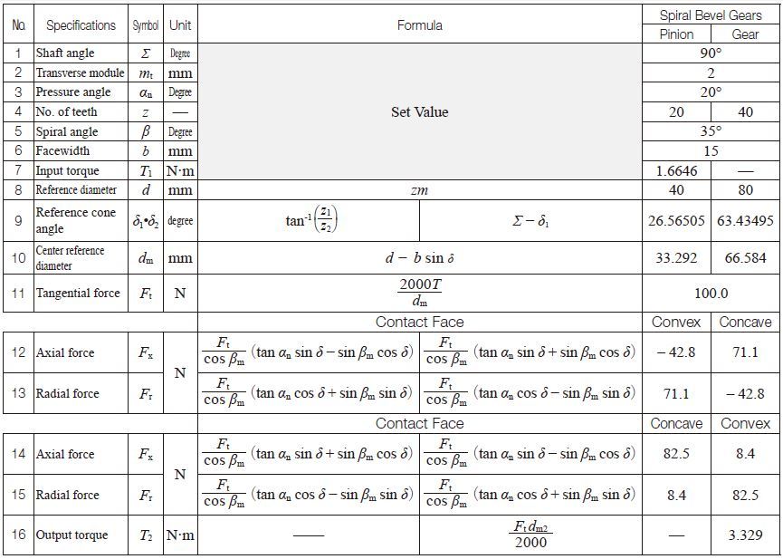
F Problem Statement and Solution Problem. Velocity factor for bevel gear is given as here C R v 56 56 v Where v is the pitch line velocity in ms. Design procedure for Bevel Gear. Finally calculate YF by Equation 1034. Gear Forces Khk Gear Manufacturer.
 Source: khkgears.net
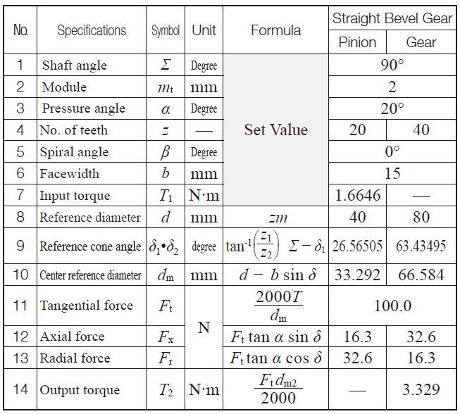
The further from the intersection of the gear and pinion axes the bigger the tooth cross sections are. Bevel gears are gears where the axes of the two shafts intersect and the tooth-bearing faces of the gears themselves are conically shaped. For bevel gearing when the number of teeth in the pinion is equal to the number of teeth in the bevel gear the speed ratio becomes 11 and these are called miter gears. Cone-shaped bevel gears are produced for the power transmission between these shafts. Gear Forces Khk Gear Manufacturer.
 Source: khkgears.net
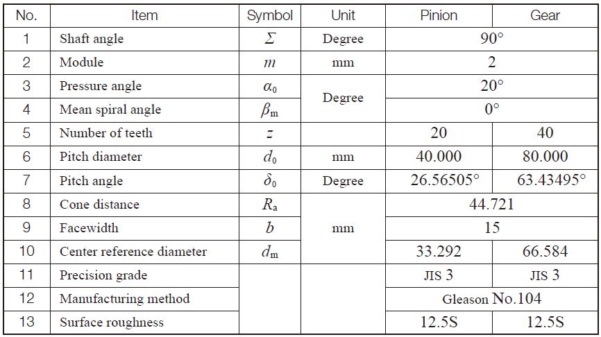
Formula of bevel gears on bending strengthJGMA403-01 The Lewis formula No. The gear durability equation is based on the Hertz contact stress equation and its application to gears. Inch Units Applicable for Constants Spur Gear Design Calculator. Bevel Gear Geometry Page 2 of 4 Tooth shape for bevel gears is determined by scaling spur gear tooth shapes along the face width. Surface Durability Of Bevel Gear Khk Gears.


